
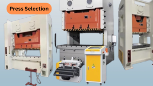
After conducting the calculation of shearing force, mechanical energy and power, the designer is in position to select a suitable press where the die is to be aimed to perform the shearing operation in question.
The most popular type of power cresses intended to shearing job are the single action, eccentric or crank driven, gap frame press or open back inclinable press or straight sided press. Presses of multiple action, and hydraulic presses are rarely used for shearing work.
The selection of the press is based on comparing the technical parameters of the particular press to the requirements in actuating the die to perform the shearing operation. Here are the parameters of the power press to be checked
1. Tonnage capacity
The mechanical presses develop their nominal or rated tonnage FN near to the bottom end of the stroke.
Therefore the point on the stroke at which the shearing begins is to be definitely below this specified point. The blanking piercing and the other shearing operations are done near to the bottom of the stroke, where the actual pressure of the press is the maximum. Shearing operation combined with forming job is done above this specified point, therefore the actual press force is less than the full rating of the cress, and careful selection is required which will he discussed later. The nominal capacity of the cress is to the higher than the sum of actual shearing force, and any other force acting vertically in the die during the shearing action like force in floating stripper, spring loaded ejector etc.
2. Fly wheel energy
A certain amount of mechanical energy is stored in the fly wheel of the press when the fly wheel rotates with its rated RPM. The fly wheel supplies all of the
energy required for the job die. energy for shearing, friction etc. by its resistance against deceleration. The driving motor then restores the loss of energy to the fly wheel-by bringing it back unto the speed in the remainder of the press cycle. For continuous operation the fly wheel may slow-down with about 10 percent of its RPM or its angular velocity; For intermittent operation the slow down can be upto
20 percent, Since the blanking piercing and any shearing operation are completed in a very short portion of the press cycle, the required mechanical energy to perform the job is generally, less than the above specified energy with 10 percent and 20 percent slow down. Therefore the energy balance of the press is not checked in the general practice.
3. Strokes per minute
The number of strokes per minute is in close connection to the number of the revolutions per minute of the fly wheel or main shaft, and this is a determined parameter of the press. In continuous work, which is possible with dies of automatic stopping system or with cropping stoppers, and with feeding device the number of strokes is equal to the RPM of the fly Wheel.
In intermittent work, which is combined with dies of simpler stopping system the number of the strokes is lesser than the RPM
The number of the actual strokes per minute is the degree of productivity, it expresses the expected output of the press job, and in incentive wage systems it is needed to determine wage standards for press operator.
As much a press tool designer is concerned in selecting press in this respect, mechanical press of higher RPM is preferred for a higher range of production, and the shearing die is to be supplied with more advanced stopping system.
4. Ram velocity
The length of the stroke, the number of the stroeks per minute, and the position in the eccentric circle determines the actual velocity of the ram. The maximum velocity is at the mid-stroke, and near to both the upper and the bottom end of the c stroke the velocity is less. Since the shearing operation is performed near to the bottom end of the stroke, the ram velocity is generally slow. In shearing operations the punch speed is of little consequence, detailed analysis is not necessary.
5. Length of stroke
Smaller eccentric cresses are built with adjustable stroke, where the stroke can be adjusted be ween S max and S min. but heavy presses are in fixed stroke. The required length of stroke S is in connection to the design of the die and the factors to be checked are the method of stopping, ejecting, stripping and the aligning system. When automatic material handling device is used longer stroke is needed, because it is actuated with the ram at a certain part of the stroke. Dies working in cut off blanks, in semi-finished pieces need longer stroke to facilitate easy handling and observation on. Shearing dies working is strip with hand feed does not need more than 10-16 mm length of strokes. S min < S < S max with long stroke care is to be taken on the sufficient length of guiding/ aligning in the die.
6. Shut height and height adjustment
The height of the die in closed position plus the parallel blocks, the additional table give the need in shut height. Both upper and lower limits of shut height are available in press catalogues.
The closed press tool is to be accommodated when its punches are 0,2-1 mm deep in the die openings in the press with ram at the bottom end of the stroke. The position of the ram can be adjusted with the screw of the connecting rod, so the shut height varies between H max to H min.
Additional details
Built in die cushion or pressure pad is needed for shearing dies with lower ejector. Positive knock out system is preferred for shearing dies with upper ejector. The distance from the vertical ram axis to the frame in gap frame presses may be. a limitation in the size of the piece. The width of opening in straight sided press, in open back inclinable press can limit the width of strip to be used.
The tie rods of large gap frame press also can limit the access to the-die with a large stock. Sufficient storing room, shelves, containers are required around the press.
Lifting hoisting devices are to be at hand to handle the heavy dies. Containers pressure air is required sometimes to discharge the component or scrap from the die.
Inclinable open back press assist in both feeding and in discharging components having the frame tilted at an angle.
Determining the Load Centre
The different forces acting in vertical direction while the shearing die performs one stroke die., Shearing force stripping force F str , force exerted by the springs in order to actuate floating stripper and ejector are F str are studied as concentrated force, but actually they are distributed force. The shearing force is distributed along the cutting edge, the stripping force similarly. The force exerted by springs is distributed one as well as it is a resultant of component concentrated forces exerted by the individual springs.
The resultant at all of these distributed forces should lie in the line of the pressing force exerted by the ram of the press, that is in the axis of the shank.
If the resultant of the vertical force acting inside the die does not coincide with the axis of the shank, a tilting can be resulted due to the eccentricity. This tilting moment M = F SH ^ . e may be very heavy because the shearing force itself is high in range of tons and ten tons. The unfavourable effects of the tilting moments are as follows:
a) elastic deformation of pillars, stripper plate in light load, plastic deformation in very heavy load.
b) displacement of punches resulting change in uniform shearing clearance in lighter cases, or interference between punch and die – edges, breakdown of edges in heavier cases.
c) wear in the stripper elate opening, wear of pillars and bushings, reducing the life of the tool resulting breakdown of edges.
d) wear in the guides of the press ram, reducing the life time of the expensive machine tool.
The eccentric location of the stripping force Fstr and that of the force of the springs results similar tilting moment, which may be less heavy, but also contribute to the wear and the deformations. It is designer’s duty to determine the position of the load centre, and to locate the shank in this position
The methods which are available to find the load centre are the different detailed geometrical constructions, the different calculations and some simplified methods. In this charter the load centre of the shearing force is to be discussed. The shearing force as a distributed load acts along the working edges which are considered as a set of elementary edges so the force is proportional to the length of the eige. Practically in shearing a stock, both the thickness of the stock and the shearing strength is constant, the only variable is the length of the edge.